Introduction
At a local antique store, I was fortunate enough to come across a couple of old Starrett indicators for a very good price. They are in pretty good shape but could use some love and attention. Both are in need of some cleaning and lubrication while one in particular need the lens reunited with the bezel assembly.


What Is A Vise?
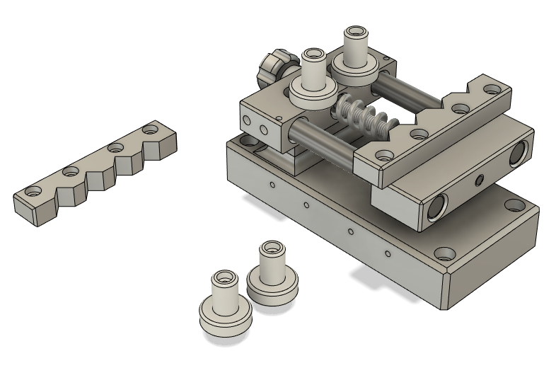
Me being the wierdo that I am, I figure there is a necessity for a proper vise to hold said indicators while they receive a much-deserved spa treatment. So, what’s a boy to do other than build one! I reached down deep in the empty cavern of my brain and the design that I came up with is the main picture of this post. If you have ever wondered how you make a small portable vise? Well here ya go!
A vise is a clamping device use to, for lack of a better word, clamp things. They come in all sorts of shapes in sizes depending on what you want to use it for. Some are stationary while others can be easily removed and clamped to another surface in a matter of minutes. There are pipe vises, machinist vises, drill press vises, and jeweler’s vises like I will be making
What Is A Watchmakers Vise?
What do you mean? It says it right there in the description. It’s a vise you stick watchmakers in…just kiddin. Really bad joke; I know. These vises are small and are specifically made for watchmakers and jewelers to hold their work so that both hands are free, and the item remains firmly in place. While I won’t be using the vise for jewelry or watches, it will be perfect for servicing indicators and other small devices. I’ve seen these made of all sorts of materials like plastic, aluminum, steel, and even brass. This would even make a good project for a 3D printer.
How Are We Gonna Make It?
My thought is to make it as versatile as possible. Its construction will be mostly that of 6160 aluminum outside of the screw that will provide the clamping force. That will be made of steel. The cylindrical jaws are used to grip on cylindrical surfaces like that of an indicator. The removable jaws will allow this to be used for holding other delicate items and will be made of plastic also. When not in use, either set can be easily screwed into the threaded holes located on the side of the base. Keeps everything neat and together.


The 2 main jaws, that I suppose aren’t really jaws, will provide a platform for the actual jaws to move in and out to contact the work. These will be milled and drilled to accept 2 chrome plated, 10 mm, hardened rods that will keep everything in alignment between the 2 jaws. Being that this device will only see extremely light clamping forces, the retaining screws through the jaws should be more than sufficient to handle those pressures.
The clamping screw is made of steel and contain features that will keep it captured in the fixed jaw. Basically, it keeps the screw retained in the fixed jaw while the moveable jaw…well…moves. However, I may create a threaded steel sleeve pressed into the movable jaw versus treading into the aluminum. I’ll cross that bridge when I get there. The adjustment knob will be out of aluminum and will contain 5 flutes for a gripping surface. I don’t have knurling tools, so any knob I make usually has this type of feature. Quite frankly, I prefer that look over knurled surfaces in most cases.


Finally, the base. Yeah, not much to say about the base. I mean…it’s a base. It will have mounting holes in case I ever decide to bolt it to a surface although that’s not the immediate plan. One thing of note is how the bottom of the base will be milled. The bottom of the base will be cut with a relief in most of the surface. The face of the 4 pads will be minimal as well as lapped to reduce any wobble when setting on a table surface.
Conclusion
This should be a fun project. Stay tuned for part 2 when I share the ins and outs of how I make this vise and the things I will undoubtedly screw up. Each part in the series will share the tools I used, setups, and other interesting tid bits. Remember to subscribe to the site, follow my content on Instagram, and of course spread the word If you like what I’m doing here.


